
racelogic traction control installation
Racelogic Traction
Control Installation
By
Derek Wang

This article explains in detail the installation
of the Racelogic Traction Control System on the US Spec MKIV Supra. This
installation article was based on a US Spec ’94 Turbo Supra with TRAC. Other
years, models, and country models may differ. Please consult your factory
service manual whenever possible
To get your own Racelogic Traction
Control in the US, contact Matrix Engineering as they’re the exclusive distributor for the
RLTCS in the US.

Tools Needed:
10mm socket wrench
Wire
cutters
Razor blade
Phillips screwdriver – Various sizes
Flathead
screwdriver
Soldering iron
Overview:
The Racelogic System monitors wheel
speed independently and looks for a difference in wheel speeds larger than a
predetermined (but tunable) threshold. Once the threshold is met, engine power
is reduced by cutting each of the six injectors independently in a rapid cycle.
They system can be adjusted to give a desired level of slip (5%, 10%, 15%, 20%,
etc). Optional features include launch control, full throttle shift, and
adjustable rev limiter.
The wires we will need to tap into are the six
injector wires, the four wheel speed sensor wires, RPM wire, ignition power, and
ground. The adjuster controller will also need to be connected via three wires,
and a serial cable can also be used to interface with a laptop computer for
data logging and additional tuning.
Installation:
Disconnect the negative battery
terminal before working on any electronics on the car
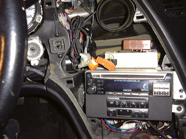
Expose the ECU in
the passenger footwall by removing the plastic carpet trim which runs along the
rocker panel under the door. This will allow for the carpet to be pulled back
after the removal of a few plastic buttons, exposing the ECU cover. Remove the 2
10mm nuts securing the cover then remove the cover. You should now be able to
see the ECU and the factory TRAC computer.
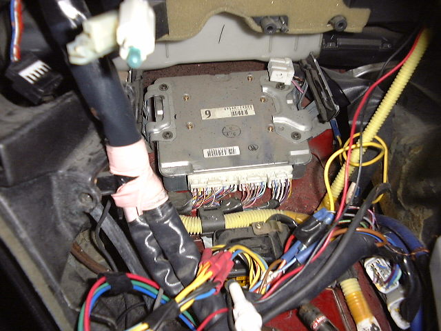
Unplug and remove the TRAC
computer. You will no longer need this with the Racelogic Traction
Control
Loosen the 10mm bolt holding the twin harness plugs onto the ECU
and remove the plugs for easier access to the six injector wires. Find the
injector trigger wires E9-15 to E9-20:

These wires will
need to be cut, one side going into the Racelogic, the other side connected to
the output of the Racelogic:
From ECU side, connect to: Red, Orange,
Grey, Green, Yellow, and Pink wires of the RL.
From firewall side, connect
to: Red/Black, Orange/Black, Grey/Black, Yellow/Black, Pink/Black.
Make
sure each injector wire has the same solid color on the ECU side as the color
striped wire to the firewall side. It is not important which color RL wire
connects to which injector
Shown below is the wiring via a Fields ECU
harness. I recommend soldering these wires and using shrink tube to protect them
from exposure:

Find the RPM
signal wire, E9-58 (Igniter), and tap the Racelogic’s black/white wire into this
signal. You do not need to cut this wire. You can use a razor blade to strip the
sleeve off a small section of the wire, then solder the RL wire and carefully
tape this up with electrician tape.
*Alternate RPM wiring –
If your car has additional
devices like the HKS VPC, Apex’I S-AFC, or any other piece that is already
attached to the E9-58 igniter RPM wire, you may experience an RPM signal drop
which will cause the Racelogic to malfunction. A good alternative is to use the
E10-16 (TACHO) wire on the ECU harness for the RLTC RPM wire:
Connect the RL’s
power wire to an ignition switched power supply. This can be found on terminal
E10-1.
Ground the RL to a good chassis ground. I used one of the ECU
mounting posts by sandwiching the RL’s ring connector on the ground wires
between the chassis, and the 10mm ECU mounting nut. Make sure you get a good
ground connection here by removing any paint that may interfere with the ground
point.
Now we’re ready to wire up the remaining four wheel speed sensor
wires. Expose the ABS/TRAC computer by removing the center dash trim pieces.
First, remove the trim piece around the shift lever by firmly pulling up on the
panel:

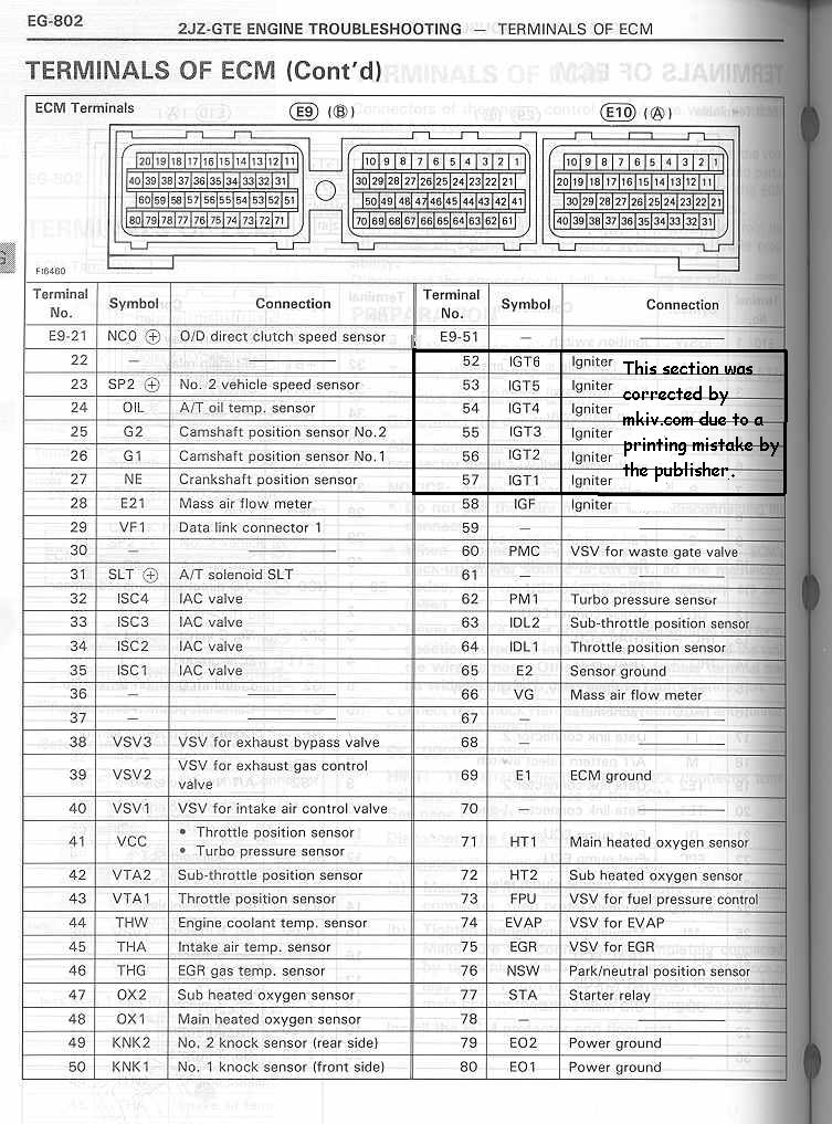
Next, remove the
odometer cluster by removing the small screws holding the cluster onto the top
of the dash:

Remove the main
trim piece which holds the clock, and the HVAC controls. Remember to unplug the
clock, the HVAC plugs, the cigarette lighter, and the traction control
button:
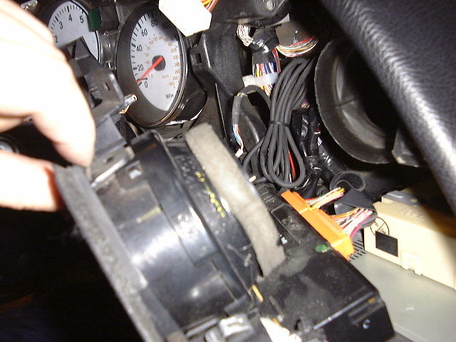
With the trim
panel removed, remove the radio and the ABS circuit box and antenna relay:
This exposes the
ABS/TRAC computer which looks like this:
Unplug the left
and the center connectors, then route them out of the dash on the driver’s side.
This will allow for more room to do the wire taps. Also, route the RL’s wheel
speed sensor loom from the ECU area to the driver side footwall by going through
the center dash:
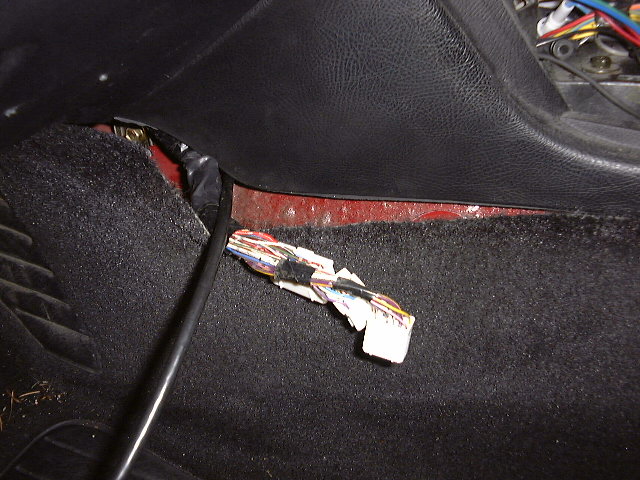
Find the wheel
speed sensor wires on the plugs which are now in the driver side footwall. We’re
looking for the (+) wheel speed sensor wires (A20-5, A20-17, A21-2, and
A21-9):
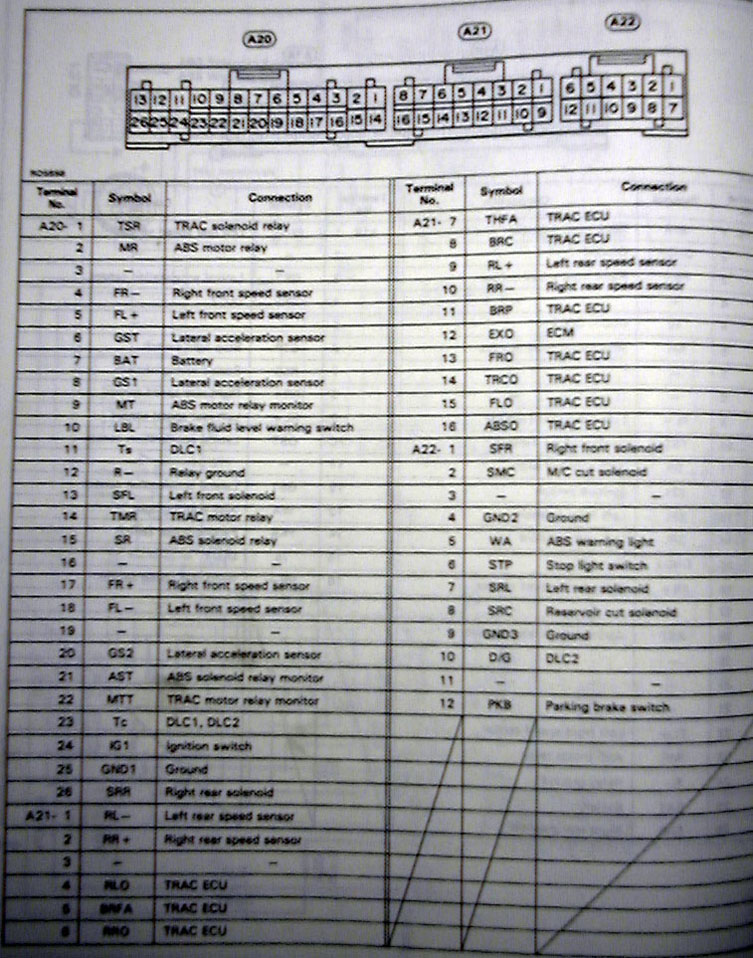
Click here for diagram of cars without TRAC
Splice
into these wires with the four RL wheel speed sensor wires similar to how you
spliced in the RPM signal wire. The order is not important:
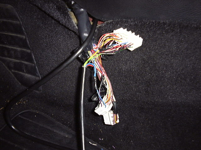
Reconnect the
plugs back into the ABS/TRAC computer:

Find an
appropriate place to install the selector knob/launch control button. Reinstall
all panels, covers, carpet, and trim in reverse order of removal. Then you’re
done!
Testing/Troubleshoot:
Ensure
all wheel speed sensor and RPM wires are connected correctly by monitoring the
green LED on different slip positions on the selector knob. Starting from “WET”,
the first 4 settings on the knob indicate wheel speed sensor input. When each
wheel is spinning, the LED will flash according to wheel speed. The faster the
wheel spins, the faster the LED blinks. Select between all four of the settings
to monitor each wheel individually. If one setting does not show a flashing LED
while the car is moving. Check your wheel speed sensor wiring.
Test the
RPM signal in a similar fashion by turning the selector to “OFF” or 20% slip.
The higher the RPM, the more rapidly the LED will flash.
Once the wiring
is confirmed, follow RL’s instructions for
calibration.
![]()
Leave a Reply