
Greddy e-manage fuel controller install
E-manage Install
on 1993-1998 Supra Twin Turbo
Shortcuts:
-
(1) –
Installing the MAF, RPM, Throttle, Power & Ground Wires -
(2) –
Installing the
Injector Wires into the E-manage
Main Harness -
(3) –
Installing the E-manage Injector Wires into the
ECU Harness -
(4) –
Installing the Ignition Wires into the E-manage Ignition
Harness -
(5) –
Installing the E-manage Ignition Wires into the
ECU Harness
(1)
–
Installing the MAF, RPM, Throttle, Power & Ground Wires
1. Remove the negative
battery cable.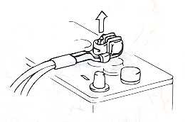
2. Remove the wiring harness
from the ECU.

3. Refer to the ECU diagram.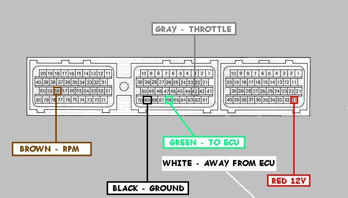
-
Splice the
BROWN
Wire (RPM) into 58. -
Splice the
Gray
Wire (Throttle) into 43. -
Cut wire 66 in half,
leave yourself enough room to connect a wire to ECU harness. -
Connect the
GREEN
wire to the 66 wire connected TO the ECU harness. -
Connect the
White
wire to the 66 wire heading AWAY from the ECU harness. -
Splice the
Black
wire (Ground) into 69. -
Splice the
Red wire (12V+) in to wire 31.
OK, Now you have all of the
main wiring
done, double check all of your connections,
reconnect the wiring harness to your ECU. Make
sure all of those wires are still tight.
Reconnect your negative battery cable. Turn the ignition to the ON position. The
E-manage
should light up.
(2) –
Installing the
Injector & Sub-Injector Wires into the E-manage
Main Harness
-
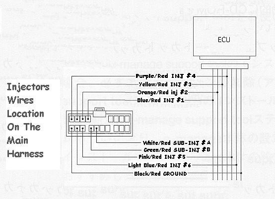
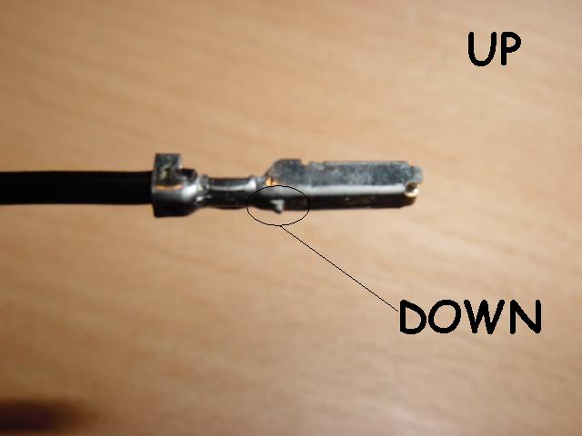
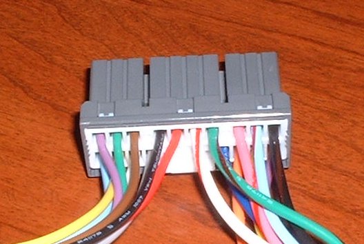
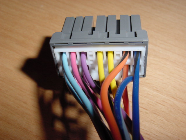
Install the injector wires into the
main harness as shown below.
-
It should look like this in the
end (without the Sub-Injector wires),


-
It should look like this in the
end (with the Sub-Injector wires),

(3) –
Installing the
E-manage Injector Wires into the
ECU Harness
1. Remove the negative
battery cable.
2. Remove the wiring harness
from the ECU.
3. Refer to the ECU diagram below.
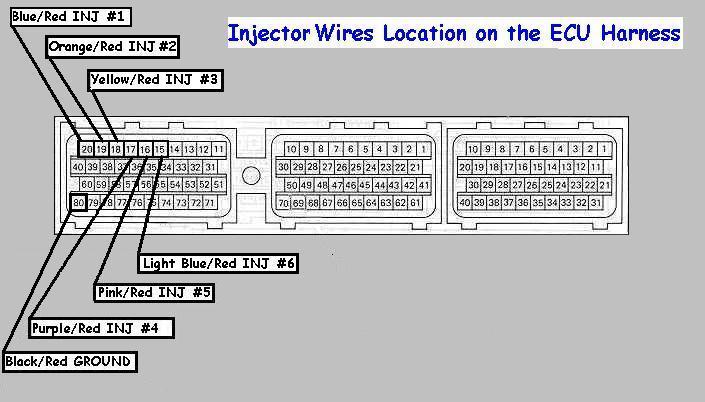
-
Splice the
BLUE/Red
(INJ#1) into 20. -
Splice the
Orange/Red
Wire (INJ#2) into 19. -
Splice the
Yellow/Red
Wire (INJ#3) into 18. -
Splice the
Purple/Red
Wire (INJ#4) into 17. -
Splice the
Pink/Red
Wire (INJ#5) into 16. -
Splice the
Light Blue/Red
Wire (INJ#6) into 15. - Splice the
Black/Red
wire (INJ Ground) into 80.
(4) –
Installing the
Ignition Wires into the E-manage Ignition
Harness
-
Install the ignition wires into the
main harness as shown below.
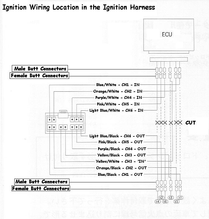
- It should look like this in the end,

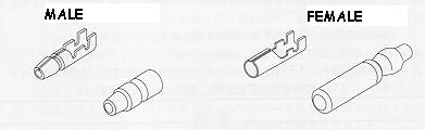
- Install FEMALE BUTT connectors on ALL the WHITE
marked wires. - Install MALE BUTT connectors on ALL the BLACK
marked wires.
(5) –
Installing the
E-manage Ignition Wires into the
ECU Harness
1.Remove the negative
battery cable.
2.Remove the wiring harness
from the ECU.
3.Refer to the ECU diagram below.
- Cut wires 57,56,55,54,53,52 on the ECU harness.
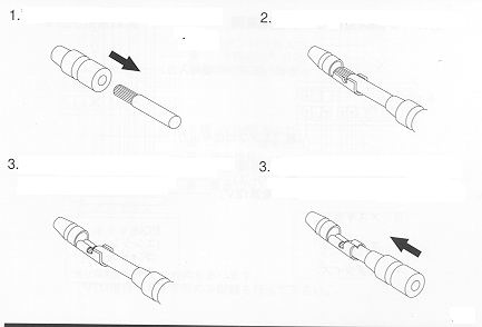
- Install MALE BUTT connectors on ALL the wires
coming from the ECU harness. - Install FEMALE BUTT connectors on ALL the
wires that been cut away from the ECU. - Start plugging the Male Connectors into the Female
as shown in step
4 above.
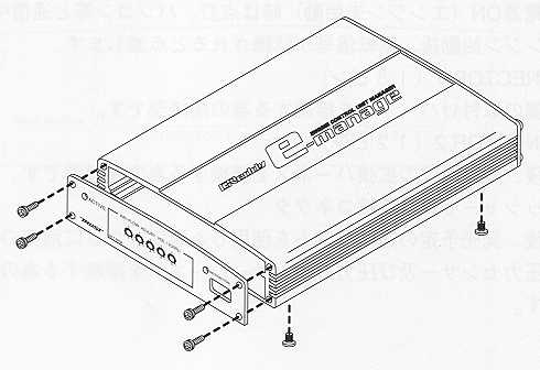
(6) – Setting the Knobs
inside the E-manage
- Remove the E-manage circuit bored from the E-manage
box,
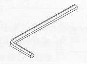
- Take off the 4 Allen screws from the front panel
with the Allen tool supplied. - Remove two bottom Philip screws.
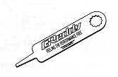
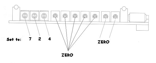
- Using the supplied Greddy tool, Set the knobs on the Left to 7,2,4, and the rest to
zero’s. - 7 = Direct ignition
- 2 = Hotwire
- 4 = Toyota Hotwire
TY_HW-5 (Toyota Hotwire Type-5)
(7) – Jumper Setting
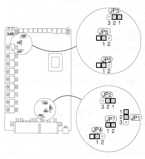
Here are all the wires installed on the
Field’s
Harness (If you are using one).


![]()
Is this the same for a 1jzgte twin turbo?
Is this install the same for a 1jz 2.5 TT ??