HKS FCD Installation Instructions (not recommended to use by mkiv.com)
Tools/parts required: Phillips screwdriver, 10mm and 12mm spanner, wire clippers, crimping tool.
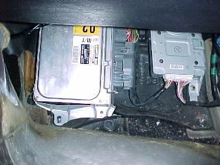
Steps: You need to remove the foot rest from the passengers footwell to expose the ECU. Undo the two phillips head snaps holding the carpet down and pull the carped back to expose the plastic foot rest. Remove it by undoing the two 10mm nuts.
The HKS FCD consists of has 4 wires:
The Red and Black wire splice into the original ECU wires. Note: The location of the correct ECU wires is found by position and not color.
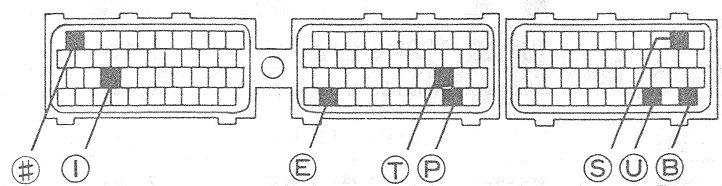
Fig 2. ECU Diagram
The yellow and white wires connect to the pressure sensing wire which must be cut (not spliced). Cut the wire a sufficient distance from the connector block, then crimp on the connectors. Yellow connects to the ECU side, white to the vehicle loom side.
|