
Category Archives: Other Mods
MKiV Twin Turbo Sequential System
One of the unique new features of the MKiV Supra was the Twin Turbo Sequential operation. Only a handful of cars touted this Sequential System. The system was designed to provide greater power levels at lower RPMs by diverting all the exhaust energies to the front #1 turbo. Since these turbo’s are rather small, running on one turbo provided a high spool characteristic. At or around 4000 rpms, the rear #2 turbo would kick in to provide for the peak potential power.
With this unique system comes complications. There are a lot of components that go into this system. If any of them malfunction, the entire system goes down. The “orchestration” of Actuators, Vacuum Switching Valves (VSVs), and vacuum lines via the ECU is a
real feat. As our beloved MKiV Supra ages, so does the Sequential System. Vacuum lines become brittle, actuators lose there ability to hold pressure, VSVs start to break down, Pressure tank loses it’s ability to store pressurized air. All of which is needed to have the system work.
Understanding this system can be somewhat complicated and difficult to diagnose. Several years ago I wrote a diagnostic manual to help people try to understand how it works and help find issues. http://97supraturbo.com/public_html/Seq%20FAQ/Seq%20FAQ.doc This doesn’t cover 100% of all possible issues, but it covers the most common. If anyone is serious to understanding and diagnosing the Sequential System, I highly recommend to purchase a MityVac hand pump. Like the MV8510 series. http://www.lincolnindustrial.com/asp/distributors/access/distributors/4_MV8510%20PIS.pdf. You will be able to test all the components with this. Find leaks, and actuator healthiness. As well as testing the pressure tank.
This all should aid you into figuring out issues. Your going to find that there is not many dealers/repair places out there that can understand and repair effectively, so the only person that can really get to it and fix things is YOU! Good Luck.
Stu Hagen
Other info
| new readers rides system!! click here to put in your entry. |
 home
home


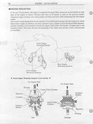
Front end popping noise cure
FRONT END
POPPING NOISE CURE
This is a HUGE VICTORY for me
and from what I hear I’m not alone in this search. Not
to slam to Toyota but I wonder if this should have been a recall….The problem was a mysterious front end popping noise emanating from the
front drivers side suspension area of my 96 Auto TT.
This popping noise occurred from a standing start, hard left right turns or
even sometimes after braking hard then starting off again. This popping
noise was always most prevalent at low speeds (2-5 mph)The confusion/ frustration starts when I started to trouble shoot my car
with only 13,000 real miles. I quickly realized that virtually this noise
could be from as many components as you could name from the Firewall
forward.Any way after several unsuccessful dealer visits, days on jack stands, nights
laying in bed sleepless thinking what could be making the noise
a buddy and I finally figured it out.Strangely enough it was the Drivers Side Motor Mount.
The cost to replace
(installed) was $119.00 but it’s free if you have Power Train Warranty.
To really isolate your individual problem, try the following (really)Have a buddy to drive the car forward and back and load up the
front end by braking at about 2-3 mph fairly hard and hold the brakes hard.Then, have him/her drive the car backward 10-15 ft and brake fairly hard
(this is not a beat the crap out of your car procedure)Be sure to be standing next to the car and walk back and forth with the car
so that you can hear the popping noise…which by the way will most likely
be more apparent going backwards during this exercise…..If you hear it under these conditions I would be 99% sure that its your
motor mount, especially if you have a well maintained vehicleIf you want to take it another step , take a wooden paint extender pole or
broom handle and have your buddy repeat the above braking drills ,
but on the reverse brake (where the pop should be occurring) walk with the
car and have the pole ‘square’ on the motor mount (with hood up obviously)
If you hear the POP and you have the pole in the right place you will
literally feel the POP up through your hand.If it does vibrate crack a beer open and celebrate….
Good luck , I hope I can save someone some major headaches and time with
this experience……….because if your like me it was a little problem
that really diminished the driving experience of such an awesome car.Now I can continue to Beat the crap out of C5’s without ‘Popping’ on launch.
Comments/suggestions? Email
me


![]()
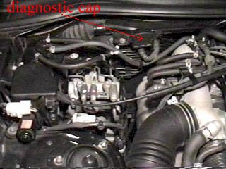
Srs airbag light on or flashing?
|
How to turn off Problem: Here’s how to turn it off : Go under the hood and open the diagnostic cap located on the
|
Targa top rattle fix
|
Targa Top Rattle As long as I’ve had my 95 TT when it gets cold the targa top would Anyway…..When I got home, I whipped out the shop manual and took So…If you have a noisy Targa, try tightening those bolts. The Eric Thanks for the Tip Eric!
|
Oxygen sensor simulator (for 96-98)
Oxygen Sensor
Simulator
Casper Electronics is selling
O2 simulator for OBD2 cars. It is about $40 and I ordered it right away to
compare with my simulator. The simulator from Casper is very small, and nice
looking with 4 wires coming out of it. I connected to battery and looked at the
signal using voltmeter. The signal appeared to be quite similar to signal that
555 timer circuit produced, but appeared more random. It should work. I haven’t
tried on my car, but looking at the signal, it looks even closer to the real O2
data that I had collected earlier. If square wave signal was enough to fool OBD2
MKIV ECU, this one will fool it too.http://www.casperselectronics.com/gp/O2SIM/index.htm
What is O2 sensor simulator?
The OBD-II cars (1996-1998) have the two O2 sensors to measure the amount of
oxygen in the exhaust gas. First sensor is measuring it right after gases escape
engine and this data is used to adjust fuel trim of the engine, as well as catch
some faulty conditions. The second sensor is located after the catalic
converter, and is used to detect the health of catalic converter. The ECU
expects the signal from the sensor to be oscillating from below 0.4v to above
0.6v, but not above 1.2v, every few seconds when cruising.
If you install the aftermarket downpipe with no cat (which as we all know is
purely for off-road applications) the ECU will detect this and indicate the
error (MIL). The ECU is quite lazy at detection, and detects this condition
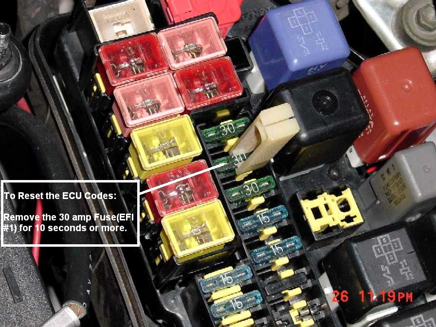
approximately during second long trip. You can reset the ECU to clear the error
code, but it’s very inconvenient, as you don’t really know if the error was
because of oxygen sensor or some important thing is wrong and needs to be taken
care of ASAP. It’s also quite annoying.
How to build Your Own Oxygen
Sensor Simulator!
The rest of the page shows how to build an oscillating signal generator with
just the right frequency and voltage to fool the ECU. It is based on classical
astable operating mode of 555 timer, so nothing revolutionary there. However we
spent few days of fiddling and testing to get the right behavior.The parts will cost about $15 – $20 from RadioShack. It’s not that hard to
build if you have some experience.Electrical diagram:
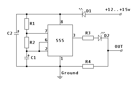
Components:
R1 100 K Ohm R2 1 M Ohm R3 100 K Ohm R4 10 K Ohm C1 4.7 uF C2 22 uF D1 1.7v@20mA LED D2 1.7v@20mA LED Hookup:
Power source Ignition, or to the ECU
PIN #1Ground One of the ground points or ECU
PIN #80OUT ECU
PIN #47 (disconnect the O2 sensor wire)Catalog part numbers from RadioShack stores:
(NOT for their online
system)
276-309 5mm wide angle red led 1.7v, 20mA 276-1723 The 555 programmable timer 276-1995A The 8 pin socket for timer chip. It makes soldering safer and
replacement easier276-150A Generic PC board 64-3052A Pack of blue tap-in connectors 278-1225 Stranded wires (black, red and green) 270-1801 Small black plastic project box 3 x 2 x 1 272-1024 Capacitor, 4.7uF 272-1026 Capacitor, 22uF
Additional notes:
If you use different flavors of 555 timer chip or LEDs with different
parameters you will need to readjust the values of R4 and R2 to get the interval
and output voltage right.
Don’t attach it directly to the ECU right after assembly. Instead attach it
to the battery and check the output. You should get approximately 0v/0.7v
flipping about every 3.3 seconds when the car is not running, and 0v/0.9v when
the car is running. The current should stay below 10mA.One LED should be always on whenever the power is supplied. Another LED
indicates when the output signal is high, so it should go on and off with the
signal.When tapping the ECU wires, triple check everything before hooking up the
oscillator. The power source should read 0v when the key is removed, about 12.6v
when they key is at ACC and about 14.3 when the alternator is running. The
resistance between ground wire and the body shield of the ECU should be 0 ohms.
And it would be best if you run the car and monitor the voltage of the original
oxygen sensor wire before cutting it to make sure you have indeed got the right
one. The resistance between ECU PIN
#47 and ground is about 1.3 to 1.6 M Ohm.The original sensor should still be dangling around, or plugged into the
downpipe. The reason is that ECU also monitors the resistance of heater circuit
inside the sensor. If you want to COMPELTELY disconnect it, you will need to
measure the resistance of the heater circuit and install the right resistor
between ECU PIN
#72 and ECU PIN
#31 Anyway, there is no need to do it if you just leave O2 sensor alone and
only intercept the oxygen signal wire.Above testing and precautions will prevent you from frying the ECU and
spending major $$$$. Anyway, I assume no responsibility if you still manage to
do so.Thanks to:
Mohd A, providing documentation
Nick P, running the
www.mkiv.com list,
Oolan Zimmer,
encouraging (and testing)
Steve V., RadioShack part numbers
Tovar
Millhollin, testing the prototypeAny
Feedback is welcome!
Problem solvers
| new readers rides system!! click here to put in your entry. |
|
|||||||||||||||||||||||||||||||||||||||||||||||||||||||||||||||||||||||||||||||||||||||||||||||||||||||||||||||||||||||||||||||||||||||||||||||||||||||||||||||||||||||||||||||||||||||||||||||||||||||||||||||||||||||||||||||||||||||||||||||||||||||||||||||||||||||||||||||||||||||||||||||||||||||||||||||||||||||||||||||||||||||||||||||||||||||||||||||||||||||||||
Trac off light + mil + cruise control dropouts + no abs lamp
TRAC Off Light + MIL + Cruise
Control Dropouts + No ABS Lamp
By John Cribb
These are mysterious, patient but well known and related problems
with MKIV Supra’s caused by cold solder joints or broken traces on certain
printed circuit boards in the dash warning lamp clusters.Symptoms:
- The TRAC Off lamp may illuminate from time to time
accompanied by a dimly lit MIL - Cruise control may stop working
- Engine warning lamps in left hand side dash pod may or
may not work at all - Any or all of these conditions can be manifested by
giving either the left or right hand Warning Lamp cluster a sharp couple of
raps with the knuckles, or pressing on them with 2-3 fingers.
The Fix:
- Removal of engine Warning Lamp pods from dash, and a
“touch up” of all exposed solder joints, along with inspection and repair of
any broken printed circuit traces.
Tools Needed:
- For the Warning Lamp cluster removal, one normal length
#2 Philips screwdriver, and one “shorty” #2 Philips are all that are required.
Magnetic tips are your friends here. - For the soldering job, a well lit work area, a 25 watt
pencil tip soldering iron, and some rosin core (not acid core) soldering paste
or flux, are required, along with 1-2 flat wooden toothpicks. The 25 watt
pencil tip iron is just about perfect for this job as it melts the solder
joints quickly, but doesn’t overheat or burn the board. A 15 watt iron doesn’t
apply enough heat and this will cause “cold” solder joints, while a 50 watt
iron will scorch the board. The toothpicks will be used to apply the rosin
flux to the solder joints.
Warning Lamp cluster removal:
- First, disconnect the negative battery terminal to
prevent airbags from inadvertently going off and/or accidental short-circuits
from occurring. - Next, get the soldering iron plugged in and heating up.
The cluster removal won’t take more than 10-15 minutes.
Now, looking up under the instrument cluster, notice there
are five (5) screws. Remove these:
This upper trim piece with the left & right warning lamp
pods & odometer can now be pulled away from the dash:
Very carefully pull this piece away from the dash until the
connectors are exposed for the right & left warning lamp pods. Find the spring
releases on these connectors and release the harness and unplug the assembly. Do
not force anything here! Once you properly release the spring catches on the
connectors, they should unplug fairly easily. Do not pull on the wires
themselves, only the plugs & sockets:
Once the trim piece with lamp pods has been removed, it’s
time to take the lamp pods off and disassemble. Here is a photo of the left hand
pod where most of the problems occur:
Remove the black screws first, which hold the pod to the
trim, then remove the brass screws which will expose the two printed circuit
boards. Disassemble the unit.
Gently spread the boards apart to expose the solder
connections. Note how the main connector for the module is mechanically fastened
to the board by its solder joints – this is one weak spot, with the connections
for the ribbon cable also being suspect:
Now, apply a thin coating of rosin core flux to all the
exposed solder joints and “touch” each one with the soldering iron so that the
solder becomes molten again and flows through the joint. Leave the iron on the
joint only long enough to ensure the solder has reflowed, then remove it. Do not
jar or move the assembly for at least 5-10 seconds after removing the iron, as
this may result in a “cold” joint. If you have done this properly you should be
rewarded with a shiny new solder joint. Note, it must be gleaming & shiny – if
it looks dull, then you moved it while it was solidifying, didn’t heat it
enough, or you forgot to use the rosin flux to keep the joint clean. The use of
rosin flux is MANDATORY for this work. The high heat of soldering causes rapid
oxidation of the metal – oxidation leads to poor bonding, and poor bonding means
cold solder joints. If your joints are not shiny, you must do them again.Repeat this process for each exposed solder joint, then
clean the excess flux off the board with a clean rag or paper towel and inspect
your work closely. Make sure all new solder joints are clean and shiny, and
ensure that no joints have accidentally shorted together by “bridging”.
If you have access to a good light source and a magnifying
glass, it may be useful to inspect the board traces closely for any evidence of
cracking or breakage as some owners have reported problems with broken traces on
their boards rather than just cold solder joints. If any broken traces are
noted, the break can usually be bridged by applying a “very” small bit of solder
at the point of the break. Keep in mind that less is best! Only apply a small
bit of solder to the tip of the iron – not even enough to make a visible “drip”
on the tip, then apply the tip to the broken trace and let the solder “heal” the
break.
Once you are happy with this cluster, repeat the process
for the right hand odometer cluster. Note how many more connections it has due
to the display:
Finally, reassemble both Warning Lamp clusters in their
pods and into the trim piece, reconnect the wiring harness and reinstall the
trim piece into the dash. Note this trim piece has several pin & sleeve type
locators on both the left & right sides, as well as the top of the gauge
cluster. Make sure these pin & sleeve points are mated correctly as the piece
will not fit otherwise and/or something will break. Replace the five (5) black
trim screws, reconnect the negative battery terminal and you’re ready to test
your work.Start the car, noting that the ABS lamp will stay on in the
left-hand pod for two seconds after the ignition is turned on (this is the ABS
self test). After this, confirm that all warning lamps have extinguished and the
car is running OK. Give both left & right pods a couple of sharp raps with your
knuckles, or apply finger pressure and see if a MIL can be produced. If this
procedure produced a MIL previously, and does not now, congratulations! Take the
car for a spin, over some railroad tracks if possible, or other rough surface
and continue to give the left & right pods some sharp raps and watching for
MIL’s or other warning lamps.If any new Warning Lamps or MIL’s are illuminated, you may
have to disassemble the dash, pull out the instrument cluster, and resolder the
joints on this assembly just as you did for the Warning Lamp pods.


![]()