
Category Archives: BPU


Electronic boost controllers(ebc) photos
| Apexi Avc-r Boost Controllers |
|
|
|

|
|
|

|
|
|

|
|
|
![mvc-904f[1].jpg (24525 bytes)](mvc-904f%5B1%5D.jpg)
|
|
|

|

|

|
|
|
![avcr[1].jpg (62051 bytes)](avcr%5B1%5D.jpg)
|
|
|
|
|
|
|
|
|

|
|
Blitz |
|
|
|
![interior[1].jpg (83180 bytes)](interior%5B1%5D.jpg)
|
|
|

|

|

|
|
|

|
|
Greddy |
|
 |
|
|
HKS |
|
|
|
|
|
|
 |
| SARD Boost Controller |
|
|
|
|


![h5[1].jpg (61691 bytes)](h5%5B1%5D.jpg)


![]()


Greddy bcc install & tune
GREDDY BCC –
INSTALL & TUNE
I.
Introduction to the Greddy Boost Cut Controller (BCC) :As the turbo pressure sensor
(TPS) on the TT Supra sees increase boost, help it sends an increased voltage
(V) on to the ECU. When typical stock boost level is exceeded, the higher TPS V
signal causes the ECU to invoke Fuel Cut; this prohibits excess boost.
The BCC is simply placed in the middle of this wire from the TPS to the ECU.
At peak-stock and lower boost levels, the BCC passes unaltered stock V
signals on to the ECU. As stock boost levels are exceeded, the BCC inputs
the too-high V signal from the TPS, but limits its output V to the ECU to
peak-stock level. Fuel cut is now not invoked at over-stock boost.Note that Greddy does not
list a BCC as made for the 93-98 Supra TT. The correct Greddy BCC to use
is labeled for the '90-'96 MR-2 Turbo, Greddy part # 15510006II.
BCC Wiring Clarification and Notes:The TPS to ECU wire is Black
with two Yellow stripes located on the larger ecu
harness. This wire is cut; the resulting cut end that goes to the TPS
connects to the BCC White input wire. The other cut end that goes
to the ECU connects to the BCC Green output wire. Most people have
cut the Blk/Ylw wire near the ECU; note that alternatively the same wire
can be found inside the wiring loom along the top/back of the engine bay.
This “away from ECU” access option is detailed in Part IV below.The BCC's Red wire
may be connected to Any ignition/switched 12V source. Therefore, it is not
necessary to cut an ECU wire for this as described in the “BCC
Install” article, although you may choose to. Other options include
access at the unused seat-heater fuse slot in the top row of the fusebox near
driver's left foot.The BCC's black wire
is connected to Any quality ground. Again, it is not necessary to cut an
ECU wire to simply ground the BCC. Other options include crimping to a
ring connector, secured firmly under a chassis bolt cleaned of paint or debris.With these connections made,
you can choose to place the BCC device itself near the ECU, under the dash, or
near the interior fuse box. One senior lister has even placed the BCC
inside the ECU .
Fields Harness Option: ( DISCONTINUED
)
Field's One Touch Replacement Harness at
www.MVPmotorsports.com
: This product is placed between the
stock male/female ECU wiring harness, to allow access without cutting any wires. Making room for this Harness also calls for
re-positioning or removing the Trac ECU (adjacent to Main ECU).
III.
Precision Adjustment of the BCC Output Voltage:Inside the BCC shell is a
screw that providesadjustment of the peak voltage output. Since the ECU
uses the TPS V data for many functions, you want this set only as low as needed
to avoid fuel cut, and not unnecessarily lower. The setting as it comes
from Greddy is usable but lower than necessary, and varies from unit to unit.
You could roughly set it by just repeatedly driving your car at max boost and
slowly turning the screw counterclockwise
to reduce the peak voltage output
until you no longer hit fuel cut. But this is a crude method compared to
adjusting it precisely by measurement with a volt meter, as follows:1.
The Connections for Voltage Tune assume your BCC is uninstalled. To Volt
tune after the BCC is fully installed, you will need to disconnect the BCC's
green and white wires to proceed, but may leave the red and black wires
installed.2.
Red BCC wire to any 12V source such as car battery +3.
Black BCC wire, and negative probe of your voltmeter, to ground of same battery.4. White
BCC wire to any automotive voltage source of 5-12V. Simplest is to
use the 12V source same as red wire. Others have used the 6V output of a
battery charger, doesn't matter because any Input of 5-12v to the BCC will give
the same Output for a given adjustment screw setting.5.
Green BCC wire to the positive probe of your voltmeter.6.
Turn screw to provide voltmeter reading of Nearly but Not More Than:
4.3 V for 93-95 cars; 4.1 V for 96-98 cars.IV.
Alternative Access of TPS to ECU wire, Away from ECU – DetailsFind the turbo
pressure sensor about 2/3 way back along top of engine intake area. It
has 3 wires coming out of it. The middle one is the Black with two Yellow stripe
wire. Now you know what the target wire looks like. Remove the top
plastic cover from the big wiring loom that runs along the back/top of the
engine bay/fire wall. The clips on this cover are a PITA to get off – use
two small screw drivers and be patient. At the driver end of the uncovered
wire loom, undo the broad electrical tape so you can SPREAD OUT and look
at EVERY individual wire. Be careful, some colors like tan, beige etc
look similar to yellow stripes. Use a bright light and look at ALL
the wires and you will find each is unique. There are Two different
wires that are both black with yellow stripes, but one is clearly bigger
around/larger gauge wire. The smaller diameter/gauge wire is the one you
want, compare it to the end you can see at the TPS. Only when you are
certian that you have identified the only correct wire, cut it. You can
then confirm it is correct by using your voltmeter set for resistance to look
for continuity between the wire you cut and the middle wire on the unplugged end
of the TPS. The end of the cut wire heading toward driver end of loom is
the TPS end for white BCC; the end toward passenger end of loom is the ECU end
for green Bcc. Pull your extension wire leads from the BCC through the
firewall passage from the interior inside by the clutch pedal, details about
this are also on boost gauge tech article. Crimp your BCC leads on to your
cut wire at the loom. Wrap your loom back up, snap the cover back on, you're
done.
Next to the
Greddy BCC install with Photos

Custom fitted apex'i air filter
Custom Fitted
Apexi Air Filter
— Install
—
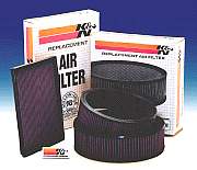
Check these Test
Results to find out why this cone filter is the “Best” for your Supra!
The New Cone
%10 better flow


Filter with gasket, sickness 3″ toilet flange, try and 3″ rubber pipe flared at both ends.
I cut off one of the ends of the flared pipes to fit onto the flange.
Estimated cost of accessories was approx $17 at local plumbing store.
Dremmeled flange to fit on the filter, buy
attached flange with gasket onto filter with 4 bolts supplied.
Attached cut end of 3″ hose to flange and filter with cl
amp that was provided on the rubber hose.
Finished product
Another angle of the finished product. This mod took approx 45 minutes and was rather easy to accomplish. Filter works great.
The Old Cone
(almost the same as the new design)


Comments/suggestions? Email
me
![]()
Downpipe installation
RMM Downpipe Installation
|


1
     
All filters were tested on a modified |
![]()